SAR Features service specifications
![]()
Find SAR Features service tutorial here.
Service Description
The SAR Features on-demand service provides a detection of changes using co-pol sigma nought and coherence from two Sentinel-1 SLC image pairs acquired before or after an event. The SAR Features service employs coherence and backscatter derived with the SAR-COIN. processor to provide an estimation of detected changes from a multi-temporal image stack of co-pol coherence and intensity images from the Copernicus Sentinel-1 mission. Three application scenarios are considered:
-
the identification of damaged structures (e.g. after earthquakes or tropical cyclones),
-
the mapping of floods in bare soil and built-up areas,
-
other disaster type or impact (e.g. landslide over bare soil).
Before executing the service, the user shall choose for which scenario the SAR Features service shall be employed (flood, or generic). Tailored preset formulas and default service parameters will be applied in the processing according to the user selection.
The service is built by chaining multiple processors. In the first part of the chain a modified version of the SAR-COIN service is executed using two pairs of Sentinel-1 SLC products (pre-event and co-event pairs). The two pairs are derived from a SLC triplet automatically retrieved by the service based on the search criteria defined by the user (same orbit state and relative orbit and contained within the AOI). The pre-event SLC pair is identified by looking for 2 the most recent SLC products acquired before the event date and the post-event SLC product is identified by looking for the first available SLC product acquired after the event date.
Secondly, the Co-located Stacking (STACK) processor is used to re-project and co-locate the ESA World Cover to the multitemporal S1 image stack and to derive backscatter and coherence differences. In this step also the image segmentation is applied using s-expressions. In particular the segmentation of coherence and backscatter differences is made using suggested thresholds or the ones selected by the user.
The derived classified raster from the change detection is then spatially filtered using the Sieve algorithm offered by the FilterVectorize processor.
Note
The current version of the service employs only Sentinel-1 SLC co-pol data.
The output product is a discrete raster providing the result from the image segmentation under the specific scenario of execution. In the Flood scenario the SAR Features change detection generates a map indicating: permanent water, bare soil flood and urban flood. The bare soil flood map is derived over not built-up areas from the binarization of co-pol backscatter differences between pre- and post-event scenes. The urban flood map is derived over built-up areas from the binarization of coherence differences between pre- and post-event scenes. Instead in the Generic scenario the SAR Features change detection generates a Coherence Change Detection (CCD) map derived from the binarization of coherence differences between pre- and post-event scenes.
The service also offers two pre-defined false color composite (R = Coherence, G = Sigma Nought secondary, B = Sigma Nought reference) defined from pre-event and co-event pairs. In a flood scenario this false composite can be used to highlight flooded areas in the early stage of the event and around the peak of the event. Areas in green indicate bare soil flood. In blue flooded vegetated areas.
Workflow
The SAR-features service implements the workflow depicted below.
Note
This service relies on SAR-COIN and FilterVectorize processors.
Input
The following inputs are needed to run the SAR Features service:
-
Sentinel-1 SLC imagery in TOPSAR (IW and EW) mode contained within the user-defined AOI and with the same radar geometry (having the same orbit state and relative orbit):
-
Reference pair: a set of two Sentinel-1 SLC images (reference and secondary) taken before the event, serving as a baseline for comparison.
-
Event pair: a set of two Sentinel-1 SLC images (reference and secondary) captured around the event date to assess surface changes.
-
The pre-event SLC pair is identified by looking for 2 the most recent SLC products acquired before the event date in the time period [event date -1 day, event date -72 days]. The post-event SLC product is identified by looking for the first available SLC product acquired after the event date in the time period [event date +1 day, event date +72 days].
Note
The same SLC product is employed in the SAR features service to derive the secondary image in the pre-event SLC pair and the reference image in the co-event SLC pair.
Third Party input:
-
Sentinel-1 precise orbits
-
COP-DEM
-
ESA World Cover
Both Sentinel-1 imagery and third party datasets are automatically retrieved by the service from the CDSE using the search parameters defined by the user.
Note
The ESA World cover is aligned and projected to the CRS of Sentinel-1 SLC data after the Terrain Correction with the COP-DEM elevation data. All datasets are then clipped to the AOI defined by the user.
Parameters
The SAR Features on-demand service requires a specified number of parameters. Table 1 describes the parameters that the user can or must set in the GUI.
| Parameter/Input layer | Description | Required | Default |
|---|---|---|---|
| Event date | Date in the format YYYY-MM-DD to be used for the selection and ingestion of pre-event and co-event Sentinel-1 SLC pairs. |
YES | |
| Area of interest | Area of interest in WKT format. | YES | |
| Orbit state | Orbit state for the search of Sentinel-1 SLC products. Select between ASCENDING or DESCENDING. |
YES | |
| Track number | Relative orbit number (integer) for the search of Sentinel-1 SLC products (e.g. 52). |
YES | |
| Event type | Type of event to analyze, affecting processing logic. Select between Flood or Generic. |
YES | |
| Coherence Azimuth Window Size | Azimuth Window Size used for the coherence estimation | YES | 5 |
| Coherence Range Window Size | Range Window Size used for the coherence estimation | YES | 20 |
| Coherence threshold | Threshold applied to coherence difference values for change detection. Insert a signed decimal number (e.g.-0.3). |
YES | -0.3 |
| Backscatter threshold | Optional threshold (dB) applied to backscatter values (mandatory for flood scenario). Insert a signed integer (e.g.-7). |
YES* | -7 |
| Filter minimum_connected_pixels | Minimum number of connected pixels for spatial filtering (e.g. 10 means filtering clusters smaller than 10 pixels). |
YES | 20 |
Note
The Backscatter threshold is mandatory only in the Flood scenario. For the Generic one it is not needed.
Event date
In the first parameter (mandatory) the user shall define the event date expressed in ISO format YYYY-MM-DD. This date is used by the SAR features service for searching input Sentinel-1 SLC products from the CDSE catalog.
Area of interest
This second parameter (mandatory) defines the area of interest to be used by the SAR features service. This AOI is employed for both searching the input Sentinel-1 SLC products and for the image stacking and cropping. The AOI geometry value shall be given in Well-Known Text format.
Orbit state
In the third parameter (mandatory) the user shall define the orbit state for the search of Sentinel-1 SLC products. In this parameter the user shall select between ASCENDING or DESCENDING.
Track number
In the forth parameter (mandatory) the user shall define the track number for the search of Sentinel-1 SLC products. Insert an unsigned integer value corresponding to the Sentinel-1 relative orbit number.
Event type
The fifth parameter (mandatory) is dedicated to the selection of the type of event to analyze which is needed by the service for triggering a different processing logic. In this parameter the user shall select between Flood or Generic.
SAR Features employed in the Flood scenario can be used for mapping floods in bare soil and built-up areas. Instead, the service in its Generic scenario is multi-purpose and can be used for instance to identify damaged structures (e.g. after earthquakes or tropical cyclones), or have an estimation of changes due to other disaster types (e.g. landslide over bare soil).
Azimuth and range window size for coherence estimation
In the sixth and seventh parameters the user shall specify the size of the shifting window for the coherence estimation in SAR-COIN. The window size is defined, in both azimuth and range directions. Being SAR-COIN designed for Sentinel-1, default values for Coherence Azimuth Window Size and Coherence Range Window Size are respectively 5 and 20.
Tip
For Sentinel-1 the Range coherence window size shall be 4 times the Azimuth one. Thus, an alternative to the default values can be having Coherence Azimuth Window Size and Coherence Range Window Size equal to 10 and 40 respectively.
Coherence and backscatter thresholds
The eighth and ninth parameters are dedicated to the image segmentation parameters. In the SAR features image segmentation the user shall define:
-
coherence difference threshold,
-
and backscatter difference threshold in dB.
Suggested values for the 2 scenarios of execution are reported in the below table.
| Parameter Scenario | Flood | Generic |
|---|---|---|
| Coherence difference threshold as a signed decimal value | -0.3 | -0.4 |
| Backscatter difference threshold in dB as a signed integer value | -7 |
Coherence difference threshold
In the eighth parameter the user shall define the coherence difference threshold to be used for the change detection with the SAR features service.
In SAR features the coherence difference is computed as:
where:
-
\(coherence_{post}\) is the co-pol coherence from the pre-event SLC pair,
-
\(coherence_{pre}\) is the co-pol coherence from the co-event SLC pair
The image segmentation is then applied to \(coherence_{diff}\) using the signed threshold defined by the user.
The expected value for the coherence difference threshold shall be a signed decimal value between 0 and 1. As an example to apply image segmentation based on a 30% loss of coherence between pre- and co-event SLC pairs the user shall insert -0.3. See Table 2 for default values suggested for the different scenarios.
Backscatter difference threshold
In the nineth parameter the user shall define the backscatter difference threshold in dB to be used for the change detection with the SAR features service. This parameter is required ONLY in the Flood scenario and therefore is not needed in the Generic one.
The backscatter difference is computed as:
where:
-
\(sigma0_{post}\) is the co-pol sigma nought in dB from the secondary image in the co-event SLC pair,
-
\(sigma0_{pre}\) is the co-pol sigma nought in dB from the reference image in the co-event SLC pair.
The image segmentation is then applied to \(sigma0_{diff}\) using the signed threshold defined by the user.
The expected value for the backscatter difference threshold shall be a signed integer comprises between the dynamic range of Sigma nought co-pol in decibel. As an example to apply image segmentation based on backscatter loss of 7db between pre-event and post-event co-pol Sigma0 the user shall insert the value -7. See Table 2 for default values suggested for Flood scenario.
Warning
The backscatter difference threshold parameter is not needed when employing SAR features in the Generic scenario and thus can be left blank.
Minimum connected pixels
In this parameter the user shall specify the minimum number of connected pixels to be used in the Sieve spatial filtering. As an example 10 means filtering clusters of pixels having size up to 10 pixels.
Tip
For a light or medium spatial filtering you can set 20 or 10 as threshold respectively. Default value: 20.
Warning
The Minimum connected pixels value shall be an unsigned integer value higher than 1.
Output
The SAR Features service generates in output the following products:
-
pre-event coherence in VV polarization (
1.coh_c_vv_YYYYMMDD_YYYYMMDD), given as single-band raster in COG format, -
reference sigma nought (dB) in VV polarization and from the pre-event SLC pair (
1.s0_db_c_vv_ref), given as single-band raster in COG format, -
secondary sigma nought (dB) in VV polarization and from the pre-event SLC pair (
1.s0_db_c_vv_sec), given as single-band raster in COG format, -
co-event coherence in VV polarization (
2.coh_c_vv_YYYYMMDD_YYYYMMDD), given as single-band raster in COG format, -
reference sigma nought (dB) in VV polarization and from the co-event SLC pair (
2.s0_db_c_vv_ref), given as single-band raster in COG format, -
secondary sigma nought (dB) in VV polarization and from the co-event SLC pair (
2.s0_db_c_vv_sec), given as single-band raster in COG format, -
co-located ESA World Cover (
3.worldcover) given as single-band raster in COG format, -
SAR features classified map (
sar-features-map-filtered), given as single-band classified raster in COG format.
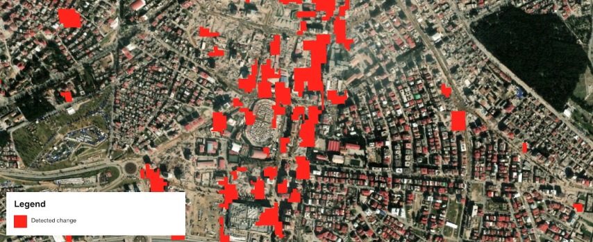
Concerning the SAR features classified map, in the Generic scenario the service provides in output a binary raster having the following classes:
-
0 - No change (transparent)
-
1 - Change (red)
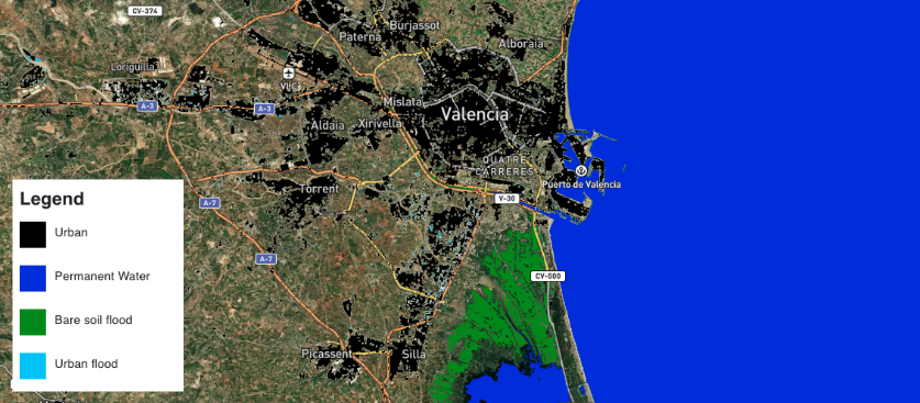
Instead in the Flood scenario the service provides in output a discrete raster having the following classes:
-
0 - Other (transparent)
-
1 - Permanent water (blue)
-
2 - Bare soil flood (green)
-
3 - Urban flood (light blue)
SAR features product specifications can be found in the below tables.
| Attribute | Value / description |
|---|---|
| Long Name | Sigma nought product from Reference SLC Dataset |
| Short Name | 1.s0_db_c_vv_ref , 2.s0_db_c_vv_ref |
| Description | Single-band geophysical asset representing geocoded Sigma Nought in dB from Sentinel-1 SLC data employed as reference for pre-event and co-event pairs. |
| Data Type | Float 32 bit |
| Band | 1 |
| Format | COG |
| Projection | UTM / WGS84 |
| Units | dB |
| Attribute | Value / description |
|---|---|
| Long Name | Sigma nought product from Secondary SLC Dataset |
| Short Name | 1.s0_db_c_vv_sec , 2.s0_db_c_vv_sec |
| Description | Single-band geophysical asset representing geocoded Sigma Nought in dB from Sentinel-1 SLC data employed as secondary for pre-event and co-event pairs. |
| Data Type | Float 32 bit |
| Band | 1 |
| Format | COG |
| Projection | UTM / WGS84 |
| Units | dB |
| Attribute | Value / description |
|---|---|
| Long Name | Coherence product |
| Short Name | 1.coh_c_vv_YYYYMMDD_YYYYMMDD , 2.coh_c_vv_YYYYMMDD_YYYYMMDD (where YYYYMMDD is the date of Reference and Secondary SLC) |
| Description | Interferometric coherence derived from Sentinel-1 SLC data for pre-event and co-event pairs. |
| Data Type | Float 32 bit |
| Band | 1 |
| Format | COG |
| Projection | UTM / WGS84 |
| Valid Range | [0 - 1] |
| Attribute | Value / description |
|---|---|
| Description | Co-located single band LC asset from projected ESA World Cover data. |
| File Name | 3.worldcover |
| Geospatial Data Type | Raster |
| Data Type | Float32 |
| Band | 1 |
| Format | COG |
| Projection | UTM / WGS84 |
| Attribute | Value / description |
|---|---|
| Description | Spatially filtered SAR Features calssified map as binary single band raster |
| File Name | sar-features-map-filtered |
| Geospatial Data Type | Raster |
| Data Type | Float32 |
| Band | 1 |
| Format | COG |
| Projection | UTM / WGS84 |
| Fill Value | Native (e.g. 0 for binary mask) |
Service Provider
The service is developed by Terradue.
References
-
ESA Science Toolbox Exploitation Platform, SNAP Toolbox available at https://step.esa.int. ↩
-
SNAPISTA, SNAP GPT Python wrapper documentation available at https://snap-contrib.github.io/snapista/. ↩
-
Copernicus, "Copernicus DEM - Global and European Digital Elevation Model (COP-DEM)", available at: https://spacedata.copernicus.eu. ↩
-
ESA World Cover, global land cover product at 10 m resolution for 2020 based on Sentinel-1 and 2 data with 11 LC classes. More info at: esa-worldcover.org... ↩