kinesIS 3D Decomposition Service Specifications
![]()
Find kinesIS 3Decomp service tutorial here.
Service Description
The kinesIS 3D Decomposition (kinesIS 3Decomp) service aims to simplify the interpretation of interferometric measurements for end users by combining independent Line-of-Sight (LoS) results generated from the kinesIS service. It calculates the actual vertical (Up) and East-West (E-W) motion components, including the calculation of associated uncertainties, providing a more comprehensive understanding of terrain motion.
The service facilitates a direct and intuitive interpretation of displacement measurements by end users, regardless of their technical background, allowing a better understanding of the physical significance of terrain motion measurements. By transforming complex Line-of-Sight observations into meaningful vertical and horizontal E-W displacement components, the kinesIS 3D Decomposition service enhances usability across various geohazards domains. Furthermore, the processed output can be seamlessly integrated into downstream workflows, or decision-support systems, thereby supporting informed planning and risk mitigation strategies.
Workflow
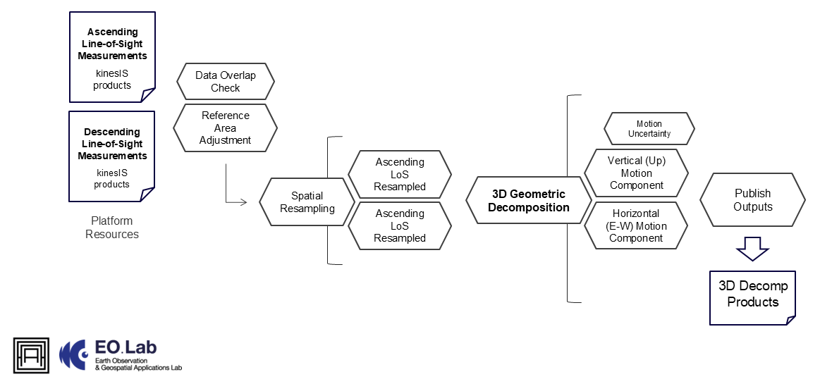
The schema shown in Figure 1 describes the high-level workflow of the kinesIS 3DDecomp service.
The core concept of the workflow is to integrate ascending and descending interferometric measurements acquired over the same observation period for a given area, enabling the calculation of actual terrain motion components1. The 3D geometric decomposition is performed using terrain motion rates for ascending and descending kinesIS service inputs, including the calculation of associated uncertainties.
The service operates with minimal user input, requiring only the definition of a local reference area to adjust the initial LoS measurements. All other processing parameters are handled automatically. The spatial extent of the outputs is determined dynamically, based on the overlapping area of the ascending and descending inputs.
The spatial resolution of the raster dataset for kinesIS inputs is expected to be consistent. Alternatively, the service will resample inputs into a grid as specified by users or based on a common spacing, enforcing the spatial resolution of the finest input raster file.
The user defined reference area for both ascending and descending kinesIS service inputs should be consistent in order to ensure proper calculations.
To perform geometric decomposition of ascending and descending InSAR measurements into three-dimensional (3D) displacement components, the following equations are commonly applied:
For ascending and descending passes, the LoS displacements can be derived from the equation below as described in Hanssen, 20012:
with:
-
\(d_{asc}\) and \(d_{desc}\) are the LoS displacements from ascending and descending orbits,
-
\(θ_{asc}\) and \(θ_{desc}\) are the incidence angles for ascending and descending orbits,
-
\(E\) and \(U\) are the east-west and vertical displacement components, respectively.
By combining the above equations, the verical and E-W displacement components can be solved.
Input
The following inputs are needed to run the kinesIS 3Decomp service:
Ascending LoS input
- Path to the kinesIS service measurements corresponding to the ascending Sentinel-1 satellite track.
Descending LoS input
- Path to the kinesIS service measurements corresponding to the descending Sentinel-1 satellite track.
Parameters
The following parameters are needed to run the kinesIS 3Decomp service:
- Output pixel size: Desired pixel size (in meters) of the output raster files
Output
The kinesIS 3Decomp service will produce the following outputs:
-
Terrain motion rates (mm/yr) in vertical direction; upward motion is expressed as positive values, while downward motion is expressed as negative values.
-
Terrain motion rates (mm/yr) in E-W direction; motion towards the East is expressed as positive values, while motion towards the West is expressed as negative values.
-
Uncertainties (in mm/yr) of decomposed measurements.
Specifications of products:
-
Definition: The expected outputs are measurements indicating terrain motion along the vertical (Up) and E-W directions.
-
Data type: Geospatial layers
-
Format: Raster files in GeoTIFF format
-
Spatial resolution: User defined (in meters)
-
Frequency: Obtained on demand
-
Spatial coverage: The service is available for the whole LAC region.
-
Temporal coverage: Depending on the revisit time of Sentinel-1 satellite units
-
Constraints: Availability of kinesIS inputs; measurements are provided over a raster grid, representing the average terrain motion within the user-defined spatial resolution.
Service Provider
The service is developed by AUTh.
References
-
Hanssen R. 2001. Radar interferometry: data interpretation and error analysis. Dordrecht: Kluwer Academic; p. 328. ISBN: 0-7923-6945.10.1007/0-306-47633-9. ↩
-
Samieie-Esfahany, S., Hanssen, R. F., van Thienen-Visser, K., & Muntendam-Bos, A. (2009). On the Effect of Horizontal Deformation on InSAR Subsidence Estimates. Fringe 2009, Proceedings of the workshop Held 30 November - 4 December 2009, in Frascati, Italy. Edited by H. Lacoste. ESA-SP Vol. 677. ISBN: 978-92-9221-241-4. ↩